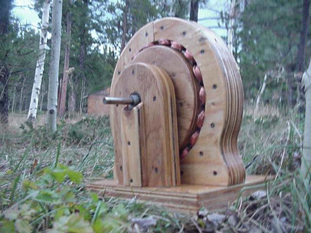
You're probably thinking that wood isn't exactly the most promising conductor of electricity so you're doubting this alternator's effectiveness. This project will provide you with as many as 500 watts running at 500 rpm for a low cost. If you wanted more voltage, you could simply make the structure larger. It's up to you!
Initial test results–wired in series, reaches 12 volts for charging at 120 rpm, with 6 amps charging current at 300 rpm. Wired in parallel, reaches 12 volts at 240 rpm, with 12 amps charging current at 350 rpm. At 500 rpm it produces about 500 watts. Unfortunately this is the limit of our current testing rig–we need to build a bigger one. More tests and a chart to come!
Parts and supplies used
- 10″ long piece of shaft, 1/2″ diameter.
- 2 1/2″ inner diameter ball bearings
- 18 surplus NdFeB rare earth magnets
- 3/4″ plywood
- 5 Pounds 18 AWG magnet wire
- 1 1/2″ drywall screws
- 3″ deck screws
- Epoxy
- Super Glue
- Fiberglass resin for final finishing
I cut out 5 plywood disks on a bandsaw, 9″ diameter. In the center of each disc I drilled a 1/2″ hole. These disks are laminated on the shaft to build up the armature. In order to hold the armature securely to the shaft, I drilled a hole about 4″ from one end 1/8″ diameter, and inserted the a pin, 4″ long. On one disk I routed a slot, 4″ long and 3/16″ wide, 3/16″ deep, to accept this pin so that it would be locked to the shaft. I generously coated the plywood discs with wood glue and clamped them together on the shaft, then screwed them together with 3″ wood screws.
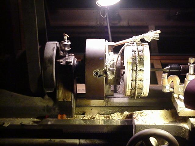
On the metal lathe (a wood lathe would work fine) I evened up the armature so that the diameter is approx 8.75″. In the center of the armature I cut a slot 3/16″ deep exactly wide enough to accept the magnets (1.74″). The magnets are laid in with alternating poles facing up. This particular magnet is available with either North or South on the outside. This alternator requires 9 of each variety. The diameter is such that the magnets stick out from the wooden surface of the armature, so the total diameter, magnets included of the armature is just short of 9.25″. These magnets have an arc much more acute than that of the armature, so it looks kind of “lumpy”! I don't think this is a problem. Custom magnets simply cost too much, it often pays to work with that which is available. In order for 18 magnets to fit around the armature, there is a small space between each magnet (approx 0.10″). For spacers, I used 1″ drywall screws, which were removed after the glue dried.
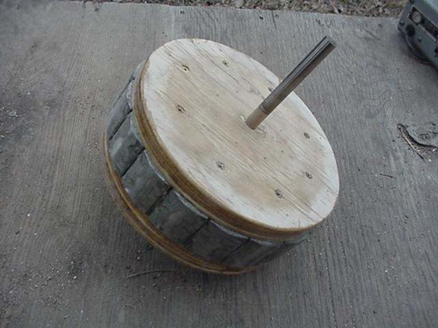
Once all the magnets were pressed in place, properly spaced with screws, I glued them in with epoxy. As a clamp, I simply tied a rope around the magnets and tightened it with a stick through the knot. When the glue started to set up hard, I removed the screws and applied a new coat of glue over the entire surface of the alternator.
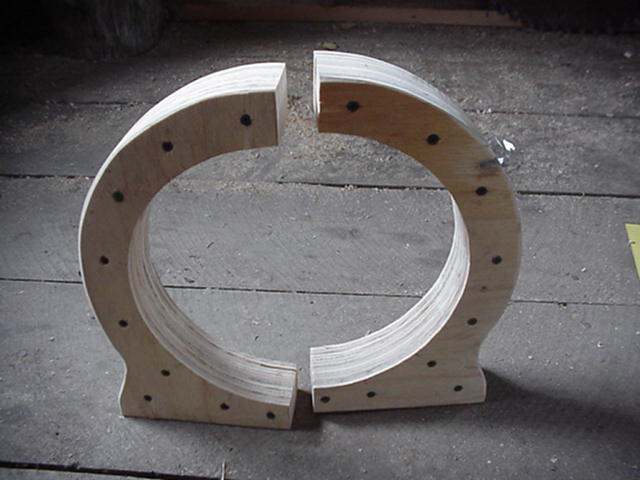
The stator (that part which will eventually hold the coils of wire) is built up of 3/4″ plywood. The inner circle has radius of 5″, which leaves room for coils between it, and the armature. The magnets protrude from the wooden alternator approx 1/8″, so this allows for coils to be approx 3/8″ thick and have close clearance with the magnets. A very small gap between coils and magnets is important, especially if the coils do not have a ferrous core. I cut pieces to build up the stator from the plywood and glued them together, clamped them tight and screwed them together with 1 1/2″ drywall screws. Each piece is made up of 3 laminates, for a total thickness of 2 1/4″.
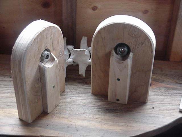
The shaft is supported by pillow blocks, also built up from 3/4″ plywood pieces. I cut holes with a 1 1/2″ hole saw to accept the bearings. Of course, the bearings have 1/2″ inner diameter to accept the shaft. The outer diameter of the bearings is roughly 1.6″ inches – a very tight press fit into the holes in the plywood. I coated the outside of the bearings with epoxy and pressed them in with an arbor press(a vice, or hammer should work fine too), as deep as possible so that I could still tighten the set screws.
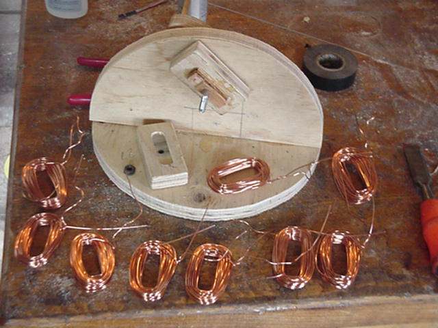
I built a simple coil winding device to speed production. It has a crank on one side, and a spool on the other. I used a long bolt as a shaft, and the end of the spool is held on with a nut. Each coil is wound on the form, then the nut is removed…so that the end of the spool comes off and the coil can be removed. It went very quickly! Since the alternator has 18 magnets, I wound up 18 coils. The coils are of AWG 18 enameled magnet wire, each coil has 50 wraps. The coils are approx 2.75″ X 1.5″ on the outside, and the hole in the middle is approx .5″ X 1.5″….as per the size of the spool on the winding machine. I thought this was an appropriate size, considering the size of the magnets. Really – it's somewhat of an intuitive guess…
When the coils come off the winding machine, they are fairly loose, and delicate. I handled them carefully before gluing them into the stator laminates.
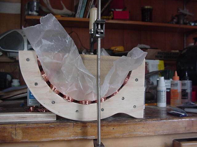
For the first step in attaching the coils I measured out their proper location (they must be spaced evenly) and lightly tacked them in with super glue. Then I generously coated them with super glue (epoxy would also work fine…it would just take longer), covered them with wax paper, and clamped them in using a form I cut from wood. Once the glue was dry, I removed the clamp, the wooden form and the wax paper, and was pleased to find they fit very well! There is also an advantage to “air cores” inside the coils–the alternator will not cog at all until under a load, which eliminates much vibration and will help the alternator start spinning in some applications.
After the coils are glued in, all that remains is sanding and finishing.

To view the rest of the steps, click here!
Have you been able to make this wooden alternator? Are there any improvements you would make to it?
Article and Photo Source: Other Power
i need to build one
Jason
why build this an alternator does not produce current
How interesting, it makes over 500 watts of power. Very cool.
Like junkyards won’t be around.
Brent Inghram
Interesting project that might be good to get a thorough understanding of how alternators work. Just be sure to build it while there is plenty of fuel for the generator to run the large power tools needed to fabricate it.
A fire waiting to happen.
Heath Marciszewski
Russ Smith
…Interesting study would be to find out the effect of magnetic field on termites…
D.W. Dixon
Robert
Kevin Robert Wright
Dan Shaw …. interesting project
Oedis Blanks
Tom Woods
Lol
Brian
Tim Monnot