The steps below will provide detailed guidance as you create this mobile workbench. It's also a unique and special gift idea for someone who loves woodworking. It does require some experience with tools so if you're unsure about how to use some of the below materials, just ask a friend or neighbor who is more competent!
Step 1: Tools and Materials
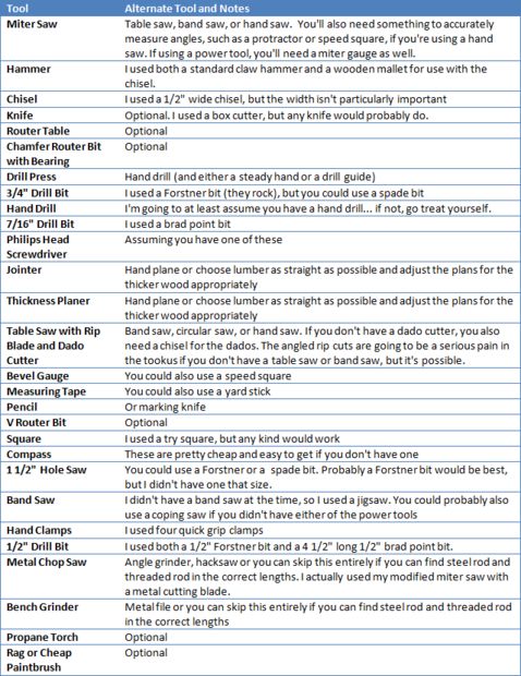
TOOLS:
MATERIALS:
- (3) 8′ 2x4s (as straight and knot free as you can find)
- (1) 8′ 1x4x8 pine board (as straight and knot free as you can find)
- (1) 13 1/2″ 2×6 (I had some lying around as scrap)
- (2) 1/2-13 x 3 1/2″ bolts (I used hex bolts, but carriage bolts would also work)
- (1) 1/2-13 x 5″ hex bolt
- (4) 1/2″ flat washers
- (3) 1/2-13 lock nuts (I used class C, but it shouldn't matter which kind)
- (1) 5/8-11 thread knurled push button nut
- (2) 5/8-11 lock nuts (I used class C, but it shouldn't matter which kind)
- (1) 5/8-11 x 12″ threaded rod
- (2) 7/16″ x 12″ smooth steel rods (I ended up getting 35″ long ones and cut them to length)
- (1) 1/2″ x 0.014 round brass tube
- (1) 3/4″ x 48″ wooden dowel (you won't need the entire length)
- (2) #6 x 1 1/2″ Phillips flat head wood screws (although you can use something similar)
- (1) 2″ diameter dowel (see below)
- (2) Wooden wheels
- (1) 1/2″ diameter neodymium magnet (a different size will work as well)
- (4) 4d finish nails
- Wood filler
- Wood glue
- Small tube of acrylic paint (color unimportant)
- Epoxy
The most specialty part of the materials is the 5/8-11 knurled push button nut. I was able to get that from Amazon, but you can also get it from MSC Direct.
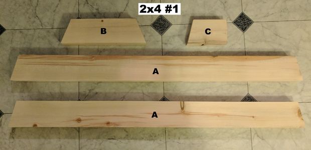
Step 2: The Pieces and Cutting Diagrams
First off all the 2x4s from here (with one exception) were dimensioned to 1 3/8″ x 3 3/8″.
The pieces you will need are:
- 2 x A – Top beams
- 3 x B – Rear vise plate and rear stretcher
- 2 x C – Front leg spacers
- 1 x D – Beam spacer. Note: this is the one piece that will be left at its original 1 1/2″ thickness
- 1 x E – Rear leg
- 1 x F – Front left leg
- 1 x G – Front right leg
- 2 x H – Work bench top pieces
- 1 x I – Front vise plate
I would cut the rough length of the beams and legs before dimensioning, while the rest of the pieces I would dimension the cutoffs first and then cut them to length. The pictures show how you can cut each of the boards to get the pieces you need.
Step 3: The Vise Back Plate and Rear Stretcher
This is a small piece, but is the most complicated part of the build. Once you've got this part down it should be pretty smooth sailing from there.
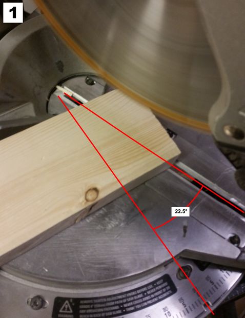
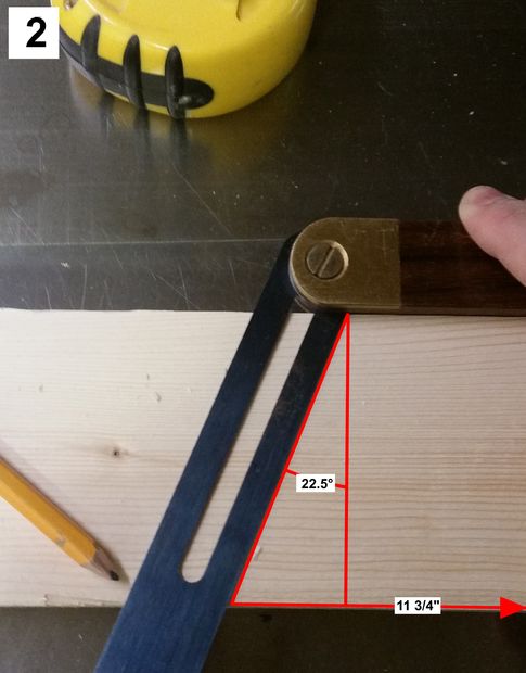
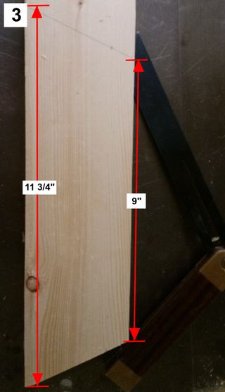
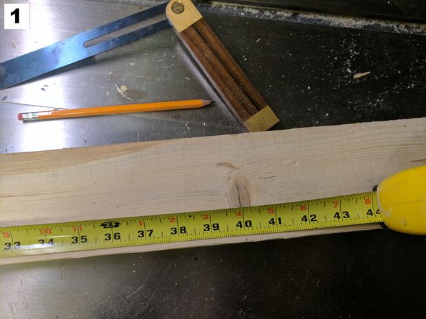
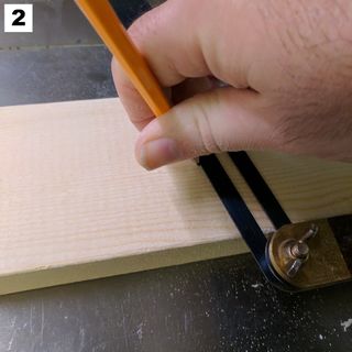
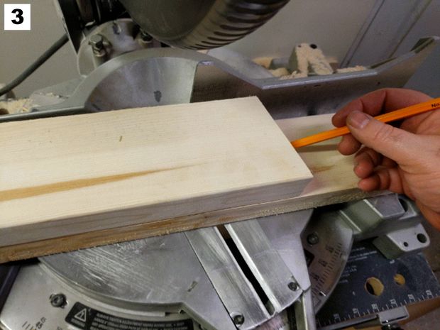
The first thing you'll need is two of the vice rear plate pieces (B). One end is cut on a 22 1/2° angle (Fig 1). Most miter saws should have a stop for that angle since it's the one required for constructing octagons. You could also use a miter gauge with a band or table saw, or a speed square or protractor with a circular or hand saw. You will then measure 11 3/4″ from the base of the previous angle and mark another 22 1/2° angle (Fig 2) to form a trapezoid 11 3/4″ at the base and approximately 9″ at the top (Fig 3). Now cut that with your miter saw. I'm a big believer in Norm Abrams saying, measure twice, cut once, but don't measure at all if you don't have to, so I then used the first piece to mark the second piece of the vise back plate (Fig 4). You can also use this as a template for the rear stretcher, since that's the same (B), and set that aside for later.
Now that you have both pieces of the rear vise plate (Fig 5), you will need to mark the halfway point at the base of one of them at 5 7/8″ (Fig 6). You'll want to double check that this measurement is in the center. Next, from the center mark you made, you will measure up 3/4″ with your square (Fig 7).
I determined that my 1 1/2″ hole saw was the perfect size for the push button nut (Fig 8). A Forstner bit probably would work better if you have access to one. I then chucked the hole saw into my drill press (Fig 9) and drilled to it's maximum extent of 7/8 of an inch (Figs 10 & 11). I then chucked a 3/4″ Forstner bit into my drill press (Fig 12) and centered it on the hole made by my hole saw. If you used a Forstner bit in the previous step you will have an even easier job of it by just lining up the 3/4″ bit with the central divot left by the 1 1/2″ Forstner bit. I then proceeded to drill all the way through the piece (Figs 13 & 14). Note that I've discovered that you get less tear out if you drill to just the point where the central point of your Forstner or spade bit just protrudes out the side and then flip the work piece over, use the small hole to center, and then drill through the undrilled side.
With the side that has the 1 1/2″ hole facing the second piece, I lined up the piece that I had been working on with another part (B) and used painters tape to hold them together in an aligned position. Run a finger along the seam between the two pieces to check for alignment because your finger is more sensitive to a misalignment than your eyes are. Now that you have the two pieces aligned, use the 3/4″ hole drilled previously as a guide for drilling into the second piece (Fig 15). I only drilled part way into the second piece, because I wanted to use the divot as a center point for my 1 1/2″ hole saw. I then removed the tape, chucked my 1 1/2″ hole saw back into the drill press and drilled 1/4″ down. Then I switched out the hole saw for my 3/4″ bit (Fig 16) and drilled through the rest of the way.
We will now need to make a hole at the bottom to accommodate the button in the push button nut. I took the first piece (the one with the deeper 1 1/2″ hole), and flipped it so that the base was up and the large hole was facing me. I then marked 3/8″ from each side of the center point (giving me a 3/4″ spacing altogether) and used my square to draw lines going one inch up (Fig 17). I also joined these two lines at the top. The thickness of the wood should be quite thin here, so you should have no difficulty scoring through the lines you marked with a knife (Fig 18) or the corner of a chisel. At this point you can lightly score the line at the top.
Using the lightly scored line at the top, drive a chisel into it (Figs 19 & 20). If you used a Forstner bit, this will be a very short way down. Even with using a hole saw, the waste in the hole parted very easily and cleanly (Fig 21).
The next process will be unnecessary if you used a Forstner bit. If you used a hole saw, like I did, you will turn to the second piece and score a number of lines along the grain of the wood into the circle outlined by the hole saw (Fig 22). Then, using a very shallow angle, use the chisel to remove the waste inside the circle (Fig 23).
The two pieces of the rear plate should now have mating holes (Fig 24) for the push button nut to sit in (Fig 25). With the push button in place, put the two pieces together and make certain that they fit together. If the nut prevents a tight fit, remove some more waste from the shallower hole until the two faces sit flush. The button on the push button nut is not attached to the nut, so at this point you should remove the button and spring and put them in a safe place. Once the two pieces fit flush (Fig 26), It's time to mix up some epoxy and glue the push button nut into the deeper of the two holes (Fig 27). Once that's been done, spread some more epoxy on the exposed side of the nut to glue it to the other piece (Fig 28). Now run a bead of wood glue on one of the mating faces (Fig 29) and spread it as a thin layer over the face (Fig 30). Make sure the two pieces are correctly aligned with your finger again and then clamp the two pieces together (Fig 31). You will want to be absolutely certain that the glue has completely cured before embarking on the next step.
When the glue has completely cured (I waited 24 hours), I removed the clamps (Fig 32) and set the rip blade in my table saw to 15 degrees (Fig 33). A band saw with a tilting table will also work as will a hand saw, but you'll need to be pretty good with a hand saw to get a nice looking cut. This will be on the inside of the workbench, however, so you could probably get away with something less than perfect. You will then trim cut the side that had the shallower hole. Do not cut the angle on the face that is closest to the nut! On the table saw, that means that the side closest to the nut will be against the fence and the side furthest will be towards the blade. You will also want to make the cut so that the blade lines up with the edge along the top of the trapezoid (short end) and angles in towards the base of the trapezoid (long side). Even keeping my blade up to the highest level it would go, it wasn't quite enough to cut all the way through the piece (Fig 34). You could finish the cut with a hand saw, but I flipped the piece over, carefully lined up the previous cut (Fig 35), and then finished the cut (Fig 36). Obviously, if you are using a band saw or hand saw, you won't need to make this accommodation. While I still had my rip blade mounted in the table saw, I adjusted the angle to 15° and cut across the top (short end) of the rear stretcher (Fig 37).
At this point, I changed out the rip blade in my table saw for a dado stack. Note that if you don't have a dado stack, you can make a series of cuts close together and then chisel them out. For the rear stretcher, I made two straight dados (Fig 38). These dados will go on the face that is longer from the bevel you cut along the top (Fig 37). The vise rear plate, however, will also need to make two dados at a 22 1/2° angles. Since my bevel gauge doesn't have anything for measuring angles, I locked down my miter saw at the correct angle and use it to adjust my bevel gauge (Fig 39). In this case, I measured the complementary angle of 112 1/2 degrees. I then marked out the location of the dados as shown (Fig 40). On the vise back plate the dados go on the side that you beveled (Fig 36).
To make it easier to line up the blades, I extended the marks I made on both the top and bottom of the pieces (Fig 41 & 42). As shown, the straight dados will be cut to a depth of 3/4″ for both the rear stretcher and the vise rear plate, while the angled dados in the rear vise plate are cut only half as deep to 3/8″ (Figs 43 & 44). I measured the depth of the dado blade (Fig 45), and ran a piece of scrap over the blade (Fig 46). I then checked the measurement (Fig 47) and adjusted the blade until it was the right depth (Fig 48). I then lined up the marks I made earlier with the edge of the blade (Fig 49) and used the miter gauge to push the pieces through (Fig 50 & 51). For the angled dados on the vise back plate, I adjusted my miter gauge to 22 1/2 degrees (Fig 52) and performed the same procedure with the dado stack set to 3/8″.
With those dados complete (Figs 53 & 54), The rear stretcher is now complete. For the vise rear plate, I had one more step I needed to do. I set up for a rabbet (Fig 55). This is a 3/4″ x 3/4″ rabbet on the corner of the top (short end) of the trapezoid and the back of the rear vise plate (the same side as you cut the dados). This rabbet will be cut on the vise rear plate only.
With the rabbet complete (Fig 56), you could stop at this point on the vise rear plate, however, if you have access to a router table and a V groove bit, you may optionally take one further step so that your vise can handle round stock. I set the fence so that the point of the V was one inch from the fence (Fig 57). Then I ran the piece through with the top (short end) riding along the fence. I then adjusted my fence to be two inches from the fence (Fig 58) and ran a groove on each side using my miter gauge. Congratulations! You've just completed the most difficult part of this build (Figs 59 & 60).
Step 4: The Beams
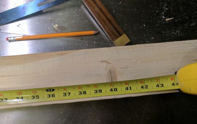
The beams (A) are 40″ long at the base (Fig 1) and are cut in the shape of a trapezoid like the vise back plate and the rear stretcher. The angles on each side are 15° (Fig 2). It's important that the beams are the same length, so I used my earlier trick of cutting one and using it to mark the second (Fig 3).
The beams will also require two front leg spacers (C). The front leg spacers are 5 1/2″ long with a 15° cut on one side (Fig 4) and are important for the front legs to spread out as well as for the vise guide rods. Once I cut the spacers, I stood them up on the flat end so that the points were facing up. Then, from opposite corners of the peak of the angle I measured a point 1/2″ down from the peak and 3/8″ from the side Fig (5). It's important that you get these pieces to be mirror images of one another. Once I made my marks, I put a 1/2″ Forstner bit in my drill press and lined the mark up with the point on the Forstner bit (Fig 6). The Forstner bit wasn't long enough to go all the way through, but it did make a nice straight guide hole for me to finish with a long shafted 1/2″ bit and a cordless drill (Fig 7) which allowed me to drill all the way through (Fig 8).
The next thing I did, was to dry fit each of the beams into the straight 1 3/8″ dados of the vise back plate while the vise back plate was on the table. Then, with the points facing down on the spacers and the holes on the beam side, I butted the spacers to the vise rear plate and clamped them in place (Fig 9). I then used a pencil to trace where the back of the spacer lined up on the beam. I then removed the clamp and the spacer, and marked where the edge of the rear vise plate comes to on the beam (Fig 10). Since the edge of the rear vise plate doesn't have an edge all along the beam, I set my bevel gauge to a 15° angle, and finished the line (Fig 11). At this point I knew the area of the beam I would need to remove to seat the spacers (Fig 12).
With the dado stack still on my table saw, I set the depth of the cut to 1/8 of an inch and set my miter gauge to 15° (Fig 13). I then extended the spacer outline up the sides of the beams so that I could line the edges up with the dado stack (Fig 14). I then cut a dado with the blade lined up on the line closest to the edge (you may want to cut two of these next to each other to make sure the angle has been covered), then I reset the miter gauge back to 0° and made a cut along the opposite line (Fig 15). I then made a series of passes as I adjusted the position of the beam to nibble away the rest of the space (Fig 16).
Once I completed this process on both beams I had the a socket in each beam to receive the spacers (Fig 17). I then put down a bead of wood glue in each socket (Fig 17), spread it in a thin layer (Fig 18), and set the spacer into the socket. Be sure to put the spacer so that the side with the hole is in the socket (Fig 19)! I then clamped the spacers to the beams and let the glue cure overnight (Fig 20). As with the vise rear plate, you want to be absolutely sure that the glue has cured before proceeding.
When the glue was cured and the clamps removed (Fig 21), I reinstalled the rip blade in my table saw, set it as high as it would go, and set the bevel to 22 1/2° (Fig 22). I set the fence on my table saw so that the blade would cut right on the bottom corner of the spacer (bottom of the beam is the widest face). I discovered later that this left the spacer too wide and I had to cut it down further. What I would advise you to do instead is to dry mount the beams in the rear vise plate and trace the edge of the beveled dados on the vise rear plate along the edges of the spacers. Since the beams should be mirror images of each other, you will need to run them along the fence in opposite directions (Figs 23 & 24). The beams should provide a large area to grasp them so that you won't need to get your fingers anywhere near the blade. As with the rear vise plate, even at the highest position of my blade I wasn't able to cut all the way through the spacers (Fig 25), so I had to flip the beams over and carefully reposition my fence so that the blade was lined up with the previous cut. When you are done, the spacer should look similar to what is shown (Fig 26).
I then remounted my dado stack so that the depth of cut was 3/4 of an inch and that it was 3/4 of an inch from the side of the beam with the spacer. I then cut a rabbet along the beam (Fig 27) and removed any of the spacer that stuck up above the rabbet (Fig 28).
The next set of steps are to allow you to use the two 1/2-13 x 3 1/2″ bolts as axles for the front legs. First, I lined up my square with the back edge of the spacers and drew a line across the bottom of the beam (Fig 29). On the opposite side of the beam, I measured from the line I drew across the bottom to 3 1/2″ closer to the edge of the beam. From this new measurement, I measured up 1/2″ and made a mark (Fig 30).
I then chucked a 7/8″ Forstner bit into my drill press and lined up the point of the bit with the mark I made earlier (Fig 31). These holes are going to be at an angle so make sure the beveled edge of the spacer is laying flat (putting the rest of the beam at the correct angle). I then drilled to an approximate depth of 1/2″ – 3/4″. This hole should be just deep enough for the head of the bolt to be dropped all the way below the surface (at an angle). Do not drill all the way through with the 7/8″ bit! Once I had the 7/8″ hole to the correct depth, I switched my drill press to a 1/2″ bit. Then I lined this bit with the divot at the center of the hole and proceeded to drill all the way through and out of the spacer (Fig 32). After that, I test fit the bolt to see if the head was completely below the surface (Fig 33). Don't worry if you drilled the 7/8″ hole a little deep. If it's a little too shallow, drill out a little more.
To view the rest of the steps, click here!
Have you built this folding portable workbench? How did it work out for you?
Article and Photo Source: Instructables